By applying force on the table and spindle and watching for movement I was able to determine that the bulk of the backlash is the result of slop in the bearing blocks. It seems as though the dials at the end of the lead-screws have worn into the mating part enough to allow the stepped down portion of the lead-screw to poke up enough to cause the slop. My remedy was to use a half-round needle file to chamfer the dial enough to allow the lead-screw to protrude further into dial. This reduced the backlash to .002 or thereabouts instead of the .015 I started with on the Z axis. I wasn't able to finish the Y axis but I hope to get to it tonight. I need to get the backlash down to .002 on all axiis so that I can convert the mill to CNC. I've got stepper motors on order so the conversion is not far away.
Friday, October 01, 2010
Still chasing backlash
By applying force on the table and spindle and watching for movement I was able to determine that the bulk of the backlash is the result of slop in the bearing blocks. It seems as though the dials at the end of the lead-screws have worn into the mating part enough to allow the stepped down portion of the lead-screw to poke up enough to cause the slop. My remedy was to use a half-round needle file to chamfer the dial enough to allow the lead-screw to protrude further into dial. This reduced the backlash to .002 or thereabouts instead of the .015 I started with on the Z axis. I wasn't able to finish the Y axis but I hope to get to it tonight. I need to get the backlash down to .002 on all axiis so that I can convert the mill to CNC. I've got stepper motors on order so the conversion is not far away.
Monday, May 17, 2010
Jury Rigged 230V for South Bend Lathe
Monday, March 29, 2010
Atlas Power Hacksaw
Friday, March 19, 2010
Bike Frame Building Course: Part 2

Day two of the bike frame course was a very exciting one. Not only was it my birthday, but I finally got to use a TIG welder, and a nice one at that. On the end of Day one I had mitered and prepped tubes to practice welding on. Toby set the amperage on the Miller Dynasty 200DX to 65 and turned on the argon. He then handed me a welding mask to protect my eyes from the bright arc and did a demo weld while describing the steps as he went. I'll do my best to describe the process, but I doubt that I can do it adequately.
First you put the tip of the tungsten up to the spot that you wish to start welding, with a gap between the tip roughly equal to the diameter of the tungsten. In this case the tungsten was 1/16". Next you press the foot pedal approximately 3/4 to full to initiate the weld. This particular TIG welder has a high frequency starting feature that makes it easier to initiate an arc. I've read that this is an important feature for welding CrMo steel because otherwise you have to do what is called a "scratch start" and run the risk of breaking off the tungsten tip into the weld area. This would leave a hard spot that would be prone to cracking.
Once the arc is started you must be sure to apply sufficient power to begin a weld pool. The weld pool is the molten puddle of steel formed when the electric arc heats the tubes being joined. It can be seen as a shiny spot that forms under the arc of the tungsten. The basic method used in TIG welding is to form the weld pool, insert the filler rod into the weld pool until the tip of the filler rod melts into the pool and makes it bigger, then move the pool toward the direction of the filler rod. This is repeated over and over along the length of the weld seem until it is complete. Before we do this though we first need to tack weld the tubes together so that they don't move much when heat is applied. This is done in the same way as described above, only you just get the weld pool started, add filler rod and then stop the weld instead of proceeding down the seam. Whenever you stop welding CrMo steel you should slowly let up on the foot pedal to allow the steel to cool slowly so that cracks don't form. Regardless of the material you should keep the torch in place after the weld until after the post-flow of argon gas shuts off. The post flow ensures that the metal is shielded from impurities in the air until the metal is fully cool. Okay, it's still frigging hot enough to burn the hell out of you, but it won't be hot enough to immediately oxidize.
The tubes used on high quality steel frame bicycles are wicked thin . This means that they are very easy to burn through. It also means that the weld pool is pretty small and can be difficult to see. The most difficult aspect to welding the frame that I found was seeing the weld pool well enough to tell when to add filler rod, when to move the arc forward, and when I burned through. I suppose it might be time to get glasses.
I made a few practice welds on the scrap tubing and I did pretty well. Certainly not as well as Toby did, but pretty darned well for my first time. You can see from my weld that it lacks the "stacked dimes" look that Toby's has. This is because I wasn't able to add the filler rod fast enough to create the ideal weld. Adding filler rod is quite difficult as it is done with the non-dominant hand, in my case the left hand. My left hand is usually used for such complex tasks as keeping papers from blowing away and filling the empty space in my left pant pocket. It should therefore be no surprise that it may take some time to get this action down to a science.Toby told me that he was surprised by how well I did considering my complete lack of welding experience. I've made some crappy MIG welds before, but these TIG welds came out so much nicer. It certainly helped that I had an instructor telling me what to do every step of the way. It was at this point that Toby said he thought that I was ready to start welding the main triangle of my bike frame together. That's right, it was judgment day.
As the main frame tubes were already
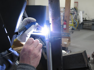
prepped for welding and placed in the jig, all we then had to do was to tack them together so that the frame could then be taken out of the jig and welded on the welding table. I tack welded each joint in about four places and Toby verified that the tacks were sufficient. We then removed the frame from the jig and placed it in a drill vise on top of the welding table so that we could orient it in a way that allowed easy access to the weld joints.The first joint that I welded was the top
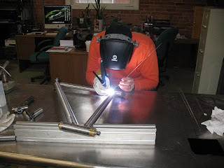
tube to seat tube junction. I'm not totally sure why we started there. I assume that it was because these two tubes have the most similar thicknesses and were therefore the easiest to weld, thus making it a good place to get my feet wet. I then did the top tube to head tube junction, the head tube to down tube junction the down tube to bottom bracket shell junction and lastly, the bottom bracket shell to seat tube junction.
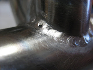
The Bottom bracket shell was pretty difficult to weld as it was much thicker that the down tube and seat tube, so it was a bit of a balancing act to apply enough heat to melt both tubes, without burning through the thinner ones. This was done partly by pointing the tip of the tungsten such that it was 2/3 on the bottom bracket shell and 1/3 on the thinner tube. This ensured that the bulk of the heat was being applied to the thicker area. There were a few instances where I did create some small holes and had to have Toby come over to fix my mistakes. This is where Toby really showed his skill and experience in filling holes I had just made in such a way as to make it barely noticeable. I was really in awe.Since it is presently more than a month since I took this frame building course the details are starting to get a bit fuzzy. As memory serves me, I was able to complete welding the entirety of the main triangle on day two. I do remember that I stayed pretty late, but it was likely because Toby and I got along really well and goofed off way more that we should have. Luckily for me I don't think that Toby had planned to leave early that week due to the fact that the North American Handmade Bike Show was coming up at the end of the week and while he wasn't going, he was letting a few of his friends use his shop to finish up some bikes for the show. Tony Maietta was finishing up a road bike with some S&S couplings that came out looking pretty sweet.
Thursday, March 11, 2010
Bike Frame Building Course: Part 1
I'm back from the bike frame building course at Hot Tubes in Shirley, MA and I am very happy with the results. The frame I produced in the class is exactly what I've been wanting, and the experience that I gained is priceless. I have no doubt that I have enough knowledge to make another frame on my own. I'm not saying that it will be as nice a frame, as I won't have anyone there to correct my mistakes in welding, or to remind me of the proper order with which to do things, but it will be a good, sturdy bike frame. It will just probably take much longer, require a lot more finish work to hide ugly welds, and will lack the impeccable paint job of a frame painted by Toby Stanton.
The whole experience was a good one. The shop that Toby has set up in Shirley, MA is quite impressive. It is located in a renovated mill that was once the home to a rope manufacturer. The brick walls, exposed beams, and large windows provide an atmosphere that really
makes going back to my cubicle in a windowless factory tomorrow even more difficult. The work are was well organized and clean. The only messes in the place were those made by me, or the two frame builders that Toby let borrow his space as they prepped frames for the North American Handmade Bicycle Show. On day one Toby and I sat down at the PC... er, iMac and designed my frame using a program called BikeCAD. The program is a user-friendly way to quickly input frame dimensions in order to spit out the necessary lengths and angles at which to cut tubes. The frame geometry that we decided to use was a cross between that used on the Ted Wojcik Monkeybutt and the Felt Nine that I demoed at Interbike East early this past fall. I decided to build it around a Fox F29 100mm fork, the dimensional specifications for which can be found on the Fox website if you really dig for them.
Once the geometry was decided upon we were able to start to set up the frame jig. The first step for doing so was to set the
bottom bracket drop. Toby's frame jig is made such that the bottom of the main member, once the table of a milling machine, is coincident with the centerline of the dropouts. That means that measuring the BB drop is a simple as using a dial caliper to measure the distance from the bottom of that main member to the center of the BB post. There is a mark on the BB post which makes it easy to find the center. The next step in setting up the jig was to adjust the angles of the arms which hold the seat tube, top tube and the head tube. This was done using a digital protractor using the main member as the reference point on which to zero the protractor.
The head tube is the first to be cut. It was rough c
ut to length using a cutoff saw with an abrasive wheel and then chucked into a lathe and faced to square off the end that was cut. The head tube is then placed into the jig between two conical pieces of aluminum that keep it centered on the rod in the front of the jig. The second tube to cut and placed in the jig in the seat tube. The seat tube is rough cut to the approximate desired length and then metered to the proper length at a 90 degree angle using a hole saw equal to the size of the BB shell. This may seem obvious, but it is far too easy to mistakenly grab the hole saw the diameter of the tube being cut rather than the one which the tube is being mitered to join.
Next we cut the top tube. The first miter wa
s made in the head tube end to ensure that there would be plenty of material at that end as it will see much more stress than the seat tube due to the long moment arm of the fork acting on it. The seat tube end is then rough cut to the approximated finish length, then mitered to the proper length. After the miter was made, as happened after each miter, the belt sander was used to deburr the outer diameter of each miter, as well as to remove the areas of the tubes that were made excessively thin by mitering them.
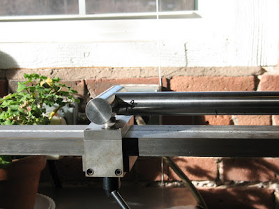
The miters in the top tube are more difficult to set up than that of the seat tube. The head tube cut was done at a 93.5 degree angle as shown on the frame blueprint above. It was cut using a hole saw equal to the diameter of the head tube.
Before the second miter can be made in the top tube we install a piece on the jig to properly orient the tube to ensure that the second miter is cut in the same plane as the first. The piece that we added to the jig is a cylinder the same diameter of the head tube and it swivels freely such that it seats fully in the previously mitered end while allowing the tube to be clamped securely into the mitering fixture. The end with the cylindrical swiveling piece can also slide up and down the fixture to adjust the length of the tube. A scale is on the top of the fixture and allows for quick setup. For this miter the jig was set at 94 degrees, a 30mm hole saw used and the length set to 584.4mm.
The down tube is mitered similarly to the top tubes, only with different angles and hole saws. The one added twist to it is that a down tube of this large a diameter not only intersects the BB shell, but also the seat tube. We approached mitering this tube by first mitering the down tube at the head tube end, then the BB end. Lastly, we used a permanent marker to roughly mark the depth of the necessary notch. The mitering jig was then set to the angle of 55.7 degrees and the hole saw plunged to saw up to the marked length.
The main tubes were then placed in the frame jig to check fit. Since the angle was set on the head tube but not the position we used the top tube and down
tube as guides to places the head tube by sliding it until it fit snugly. We then could check to be sure that all of the miters were tight and to the proper lengths. We measured the lengths of the tubes with a tape measure and inspected the miters visually. The miter in the down tube which provides clearance for the seat tube needed to be adjusted. We had to re-miter it twice to get it right, but it fit nicely when we were done.
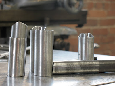
Once the fit of the main tubes was verified we prepared them for welding. The insides were cleaned using a die grinder with a sanding drum at each end. Then the inside and outsides were washed with non-chlorinated brake cleaner or lacquer thinner.
Toby had me miter a few scrap pieces of tubing to fit practice welding on. They were mitered to fit and cleaned as the main tubes were. By this time it was 7pm and we decided to call it a day.
Sunday, February 07, 2010
Hot Tubes Bike Building Course
Sunday, December 20, 2009
Taig Mill: More Upgrades
Changing the leadscrew was pretty simple. First turned unscrewed the two screws holding the bearing block on the end of the X-table. Then I turned the lead-screw out of the leadscrew nut. The leadscrew nut could then be replaced with the new adjustable backlash model. Prior to doing so I cleaned and oiled the gibbs and ways, since it was all exposed and easy to get at that point.
The next step was to remove the crank and the dial from the old leadscrew by first removing the hex nut. Be careful not to allow the key to fall out from the keyway in the shaft if you need to reuse it. It is small and can be very difficult to find on the garage floor. Not that I know, I am just assuming that this would be the case. I next placed the new bearing block on the new leadscrew and assembled the dial and crank onto the new leadscrew. The new leadscrew included a key, a washer and a lock-nut. I've read to be careful not to over-tighten then nut as this can damage the ball bearings in the bearing block. I therefore used care to tighten the nut only until I could feel no more slop in the assembly.
I did find that the key was a little oversized and needed to be filed to fit properly. Aside from that it all fit together quite nicely. One thing that I was disappointing in was the shallowness of the mark on the bearing block which one would use, in conjunction with the dial, to determine the travel of the table. If you look at the picture below you may barely be able to see what looks like a vertical scratch at the 12 o'clock position. This is not much more visible by eye than in the picture and I will have to try to scribe it more deeply later. I realize that this bearing block is intended to be used mainly on CNC machines, but if they were going to go to the trouble of marking it at all they may as well have done it deeply enough to be useful.
Further improvements I intend to make are to replace the other two leadscrew nuts, and to make and install way covers. After that I'll have to tram everything up and I'll be ready to cut some more chips on her.
Tuesday, November 24, 2009
Taig Mill From Ebay: Update
I also managed to wreck the test indicator that I was using to align the vise. I was cranking the handles to move the table to do something and I didn't remove the indicator before doing so. I tend to be really impatient and take shortcuts that end this way all too often. Luckily, the indicator was a $30 cheapy that I bought from littlemachineshop.com rather than a $200-$300 Starret or Brown and Sharp.
I did manage to machine a few pieces out of scrap aluminum that I got from work. I made a few t-slot nuts and two clamps to hold the vise down. In order to clamp the vise down to make those I ground some 1/4-20 carriage bolts to fit in the t-slots and made some clamps on the FDM machine at work. The FDM machine extrudes ABS plastic, so those clamps were not very strong and the vise walked at times, which is why I used them only to make new clamps.
Lee and I got together at his house the other Saturday. I loaded the bio-diesel processor into my truck and dropped it off in one of his garages. I presently have no diesels running, so the ambition to complete the processor is just not there. Lee now has my old Golf and a Rabitamino, so hopefully he'll find the time to get one of them going and the processor up and running too.
After we unloaded the processor we worked on fixing up an old drill press that Lee had because I had none and he had an extra laying around. The press had no power cord, no power switch, and the belt guard had no means of being mounted. Lee fashioned a quick and dirty power switch from a light switch that he hastily tore off of the wall of his garage. He then attached it using some scrap wood that was laying around. Lee doesn't pay much regard for aesthetics, but he gets results.
The mount for the belt guard was a bit more refined as Lee was itching to show me his wood lathe and used it as an excuse to start it up. The drill press is based around a large pipe Lee turned a piece that would fit into the pipe. He then attached a few blocks of wood upon which the guard rests quite nicely. It isn't beautiful but it works better than the nothing that I had before.
I actually used the drill press to drill and tap the holes in the Taig column to mount the power switch. It was much nicer than drilling a crooked hole with the hand drill. I was also able to chuck the tap and turn it by hand to start the tap straight, thus reducing the likelyhood of breaking the tap. Well done, Lee. Thanks for the drill press.
Saturday, October 31, 2009
Taig Mill from Ebay
The mill didn't fair too badly, but the end of the x-axis lead screw was bent slightly and the nut on the end of it was a bit mangled. Everything seems to be alright, but I'm debating putting in a claim since it was insured.
Below is a picture of the mangled box that the mill came in and the end of the lead screw that was damaged. The lead screw does seem to drag a little on that end, so perhaps it will be worth calling UPS.
I did my best to clean the gibbs and ways and lead screws, and that made a big difference on the way that the mill table moves. Aside from the little bit of drag on the x axis where the lead screw was bent, the table moves pretty smoothly.
It looks as though this is on older version of the Taig mill, as the color is grey not blue and the gibbs use a different adjustment method than the ones that I have seen pictured elsewhere. I think that it will work just fine for me regardless. I do need to purchase a few items before I can do much with it. The vise that was included is pretty old and crappy. I will also need to buy some t-nuts and other means of holding work down.
The motor on the mill also doesn't appear t
I'm looking forward to getting this thing up and going. I have a few designs for LED bike lights that I intend to make with it. I'll post the designs when I get around to it.
Tuesday, October 13, 2009
Bike Light Build: Part Three - Milling around

I've never really used a milling machine before, aside from using it as a glorified drill press. I decided that the bike light project was worth giving it a try. I needed to mill a 1/8" thick piece of aluminum into a 7/8" square. It was a pretty unambitious job, but you need to learn to walk before you can run, right? I won't go into a ton of detail about how I did it and whatnot, since I am by no means approaching being an expert. I am, in fact, the opposite. I know just enough to not hurt myself. Not this time anyway.
I was actually surprised at how easily the aluminum cut on the Bridgeport. My few previous attempts at milling had pretty poor results as I was trying to cut steel with dull end mills and absolutely no clue what I was doing. I have since learned a bit more of the proper technique. I still struggle with knowing which direction the slides move when you turn the handles, but I assume that I have the capacity to learn that with more experience.
I will detail later what this piece will be used for. Right now I'm just going to bask in the glow of knowing that I turned handles on a Bridgeport and got more than a squealing noise, hot discolored chips, and a mangled piece of scrap from the endeavor.


