Friday, December 21, 2007

Using a parallel interface LCD with Arduino


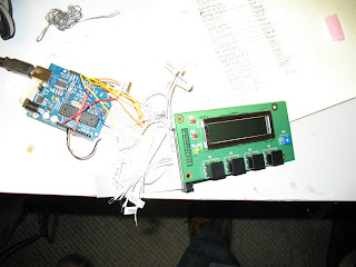
Hitachi HD44780-compatible LCD's are very cheap and readily available from many electronics suppliers, ebay, even from junk that you may find at tag sales. They are also relatively easy to use with microcontrollers, especially when using libraries that reduce the code to a few lines. There are two such libraries available for the Arduino. One is the 8 bit library and one is the 4 bit version. Both libraries end up performing the same basic function, but the 4 bit version requires much fewer digital outputs from the Arduino. This is a huge benefit if you intend to do more than just display messages on an LCD. I wired up the LCD using an IDE cable that I had leftover form and old computer. I just cut it in half, bared the wires, labeled them according to which LCD pin they corresponded with, and tined them with solder to ease inserting them into the breadboard. The labeling was done according to the spec sheet for the particular LCD that I have and the wiring was done according the page describing the 8 bit library. The only difference in the wiring for the 4 bit library is that the R/W lead was connected to ground and data bits 0-3 were not connected at all. When you download the 4 bit library there is an example program included. I modified the example code a bit to suit my tastes. The code is included after the video. Eventually I'll bother narrating these videos. Not there yet.


//example use of LCD4Bit library

#include
//create object to control an LCD.
//number of lines in display=2
LCD4Bit lcd = LCD4Bit(2);

void setup() {
pinMode(13, OUTPUT); //we'll use the debug LED to output a heartbeat

lcd.init();
}

void loop() {
digitalWrite(13, HIGH); //light the debug LED

lcd.clear(); //clear LCD
lcd.printIn("All your base"); //print "All your base"
delay(1000); //wait 1 second
digitalWrite(13, LOW); //turn off the debug LED

//print some dots individually at end of first line of text
for (int i=0; i<6; i++)
{
lcd.print('.');
delay(100);
}
//print something on the display's second line.

lcd.cursorTo(2, 0); //send cursor to the beginning of line 2
lcd.printIn("Are belong to us"); //print "are belong to us"
delay(1000); //wait for 1 second
lcd.leftScroll(20, 100); //scroll entire display 20 chars to left, delaying 50ms each inc
}

Monday, December 17, 2007

Adding Libraries to Arduino - 0010

I'm not sure if the way that libraries are setup has drastically changed since Arduino - 0004 or what, but the tutorial for using an 8 bit LCD display by using the "LiquidCrystal" library needs to be corrected. In this tutorial it says to download the zip file and then paste the "LiquidCrystal" folder into the "arduino-0004\lib\targets\libraries" folder. I assumed maybe that there was a corresponding "arduino-0010\lib\targets\libraries" folder in the latest version of the IDE. I was wrong. There is only a "arduino-0010\lib" folder. I therefore created subfolders to match the file path given, resulting in "arduino-0010\lib\targets\libraries". This did nothing for me. I then tried to just paste the library into the "arduino-0010\lib" folder but this too did not result in the library being visible in the Sketch>Import Library menu. Knowing that there were libraries already working in the Arduino IDE I did a search for *.h and found the import libraries to all be saved in the "arduino-0010\hardware\libraries" folder. I pasted the library into that folder, and presto, it worked! OK, so that's not entirely true. The Arduino IDE listed it in the Import Library menu however it gave a weird error at the bottom of the window. I then tried the 4 bit version and it shows up without an error. That's fine with me as the 4 bit requires fewer wires. I'll have to get it wired up and put up a post soon. Anyway, to sum up what I've found regarding loading libraries into the Arduino IDE(version 0010); paste them into "arduino-0010\hardware\libraries".

Saturday, December 15, 2007

Arduino POV


I´ve been wanting to make a POV(Persistance of vision) device like the one that Ladyada sells on her site for a while now because I think that they are pretty cool. For those unfamiliar with POV devices, they use the fact that images or lights remain in your vision for a small amount of time after you first see them to make a moving column of lights write text by flashing them at a specific sequence. I found the code on the Arduino playground and just changed the test at the end of the program to say ¨NOT A BOMB¨. A little bit of a dig at the Boston police department. My device looked a whole lot more like a bomb than those that caused the ridonculous bomb scare in beantown. Anywho, the code can be seen below. I´ll try to get the pictures that Lee and I took at work the other day and post that ASAP.

/*
????????????????????????????????????????????
persistence of vision typography with arduino
michael zoellner - march 2006
http://i.document.m05.de

connect anodes (+) of 5 leds to digital ports of the arduino board
and put 20-50 ohm resistors from the cathode (-) to ground.

the letters are lookup tables consisting arrays width the dot status in y rows.
????????????????????????????????????????????
*/


// defining the alphabet
int _[] = {0,0,0,0,0, 0,0,0,0,0, 0,0,0,0,0};
int A[] = {0,1,1,1,1, 1,0,1,0,0, 0,1,1,1,1};
int B[] = {1,1,1,1,1, 1,0,1,0,1, 0,1,0,1,0};
int C[] = {0,1,1,1,0, 1,0,0,0,1, 1,0,0,0,1};
int D[] = {1,1,1,1,1, 1,0,0,0,1, 0,1,1,1,0};
int E[] = {1,1,1,1,1, 1,0,1,0,1, 1,0,1,0,1};
int F[] = {1,1,1,1,1, 1,0,1,0,0, 1,0,1,0,0};
int G[] = {0,1,1,1,0, 1,0,1,0,1, 0,0,1,1,0};
int H[] = {1,1,1,1,1, 0,0,1,0,0, 1,1,1,1,1};
int I[] = {0,0,0,0,1, 1,0,1,1,1, 0,0,0,0,1};
int J[] = {1,0,0,0,0, 1,0,0,0,1, 1,1,1,1,1};
int K[] = {1,1,1,1,1, 0,0,1,0,0, 0,1,0,1,1};
int L[] = {1,1,1,1,1, 0,0,0,0,1, 0,0,0,0,1};
int M[] = {1,1,1,1,1, 0,1,1,0,0, 0,1,1,1,1};
int N[] = {1,1,1,1,1, 1,0,0,0,0, 0,1,1,1,1};
int O[] = {0,1,1,1,0, 1,0,0,0,1, 0,1,1,1,0};
int P[] = {1,1,1,1,1, 1,0,1,0,0, 0,1,0,0,0};
int Q[] = {0,1,1,1,1, 1,0,0,1,1, 0,1,1,1,1};
int R[] = {1,1,1,1,1, 1,0,1,0,0, 0,1,0,1,1};
int S[] = {0,1,0,0,1, 1,0,1,0,1, 1,0,0,1,0};
int T[] = {1,0,0,0,0, 1,1,1,1,1, 1,0,0,0,0};
int U[] = {1,1,1,1,1, 0,0,0,0,1, 1,1,1,1,1};
int V[] = {1,1,1,1,0, 0,0,0,0,1, 1,1,1,1,0};
int W[] = {1,1,1,1,0, 0,0,1,1,0, 1,1,1,1,0};
int X[] = {1,1,0,1,1, 0,0,1,0,0, 1,1,0,1,1};
int Y[] = {1,1,0,0,0, 0,0,1,0,0, 1,1,1,1,1};
int Z[] = {1,0,0,1,1, 1,0,1,0,1, 1,1,0,0,1};
int colon[] = {0,0,0,0,0, 0,1,0,1,0, 0,0,0,0,0};

int letterSpace;
int dotTime;

void setup()
{
// setting the ports of the leds to OUTPUT
pinMode(2, OUTPUT);
pinMode(3, OUTPUT);
pinMode(4, OUTPUT);
pinMode(5, OUTPUT);
pinMode(6, OUTPUT);

// defining the space between the letters (ms)
letterSpace = 6;
// defining the time dots appear (ms)
dotTime = 3;

}

void printLetter(int letter[])
{
int y;

// printing the first y row of the letter
for (y=0; y<5; y++)
{
digitalWrite(y+2, letter[y]);
}
delay(dotTime);

// printing the second y row of the letter
for (y=0; y<5; y++)
{
digitalWrite(y+2, letter[y+5]);
}
delay(dotTime);

// printing the third y row of the letter
for (y=0; y<5; y++)
{
digitalWrite(y+2, letter[y+10]);
}
delay(dotTime);

// printing the sspace between the letters
for (y=0; y<5; y++)
{
digitalWrite(y+2, 0);
}
delay(letterSpace);
}

void loop()
{
// printing some letters
printLetter(N);
printLetter(O);
printLetter(T);
printLetter(_);
printLetter(A);
printLetter(_);
printLetter(B);
printLetter(O);
printLetter(M);
printLetter(B);
printLetter(_);

}

Tuesday, December 11, 2007

Arduino Knightrider


I finally got around to ordering an Arduino from Sparkfun.com. For those of you who don't know, Arduino is an open source platform for interfacing electronic devices with a microcontroller. More information can be found on arduino.cc. I've tried to used PIC microcontrollers in the past and found that the information available is more geared towards electronic professionals, and therefore over my head. The Arduino, on the other hand, is a collaborative project designed to be used by artists to make interactive art. If an artist can use it I sure as hell can :P The programming language is based on C, which is still a bit foreign to me, so I've resorted to asking my wife to help me since she is a computer programmer by trade. One of the first projects I've decided to make is an LED sweeper, similar to the lights on the front of Kit, the car from Knighrider. I wanted to make the lights fade in and out instead of just being on or off so I used pulse width modulation, which essentially pulses the lights really quickly; so quickly in fact that the human eye cannot easily detect it. You can control the percentage of time that the light is on by assigning a value between 0 and 255. 0 is off and 255 is on. With some help from wifey I wrote the following program to sweep 4 pairs of LEDs back and forth using pulse width modulation to make the LEDs increase in brightness and then decrease back to zero sequentially and then back down the line. A picture of the circuit can be found above and a video of the resulting sweep below the code.


/*
* Loopwithfade
* by mojomoney
*
* Lights multiple LEDs in sequence, then in reverse
* using pwm to fade, creating an incandescant effect.
* In this example 4 LEDs are used
*/
int delaytime = 3; // delay time between steps
int pwmincrement = 6; // value of increment to pwm value
int x; // number of times light sequence cycles
int i; // variable to keep the actual value
int ledpin1 = 9; // light connected to digital pin 9
int ledpin2 = 10; // light connected to digital pin 10
int ledpin3 = 11; // light connected to digital pin 11
int ledpin4 = 6; // light connected to digital pin 6
int value1; // intensity of led 1
int value2; // intensity of led 2
int value3; // intensity of led 3
int value4; // intensity of led 4

void setup()
{

}

void loop()

{ for(x = 0 ; x < 10; x++ ) // makes program cylce 10 times

{ for(i = 0 ; i <= 1530; i+=pwmincrement )

{ if (i<=255)

{
value1 = 255 - i; // fade led 1

value2 = i; // brighten led 2

analogWrite(ledpin1, value1); // sets value1 (range from 0 to 255)

analogWrite(ledpin2, value2); // sets value2 (range from 0 to 255)

delay(delaytime); // waits for 30 milliseconds to see dimming effect

}

else if (i<=510)

{

value2 = 510 - i; // fade led 2

value3 = i-255; // brighten led 3

analogWrite(ledpin2, value2); // sets value2 (range from 255 to 0)

analogWrite(ledpin3, value3); // sets value3 (range from 0 to 255)

delay(delaytime); // waits for 30 milli seconds to see the dimming effect

}

else if (i<=765)

{

value3 = 765 - i; // fade led 3

value4 = i-510; // brighten led 4

analogWrite(ledpin3, value3); // sets value3(range from 255 to 0)

analogWrite(ledpin4, value4); // sets value4(range from 0 to 255)

delay(delaytime); // waits for 30 milliseconds to see dimming effect

}

else if (i<=1020)

{

value4 = 1020 - i; // fade led 4

value3 = i - 765; //brighten led 3

analogWrite(ledpin4, value4); //sets value4(range from 255 to 0)

analogWrite(ledpin3, value3); // sets value3(range from 0 to 255)

delay(delaytime);

}

else if (i<=1275)

{

value3 = 1275 - i; // fade led 3

value2 = i - 1020; // brighten led 2

analogWrite(ledpin3, value3); // sets value3(range from 255 to 0)

analogWrite(ledpin2, value2); // sets value2(range from 0 to 255)

delay(delaytime);

}

else

{

value2 = 1530 - i; // fade led 2

value1 = i - 1275; // brighten led1

analogWrite(ledpin2, value2); // sets value2(range from 255 to 0)

analogWrite(ledpin1, value1); // sets value1(range from 0 to 255)

delay(delaytime);
}

}

}

}