I'm back from the bike frame building course at Hot Tubes in Shirley, MA and I am very happy with the results. The frame I produced in the class is exactly what I've been wanting, and the experience that I gained is priceless. I have no doubt that I have enough knowledge to make another frame on my own. I'm not saying that it will be as nice a frame, as I won't have anyone there to correct my mistakes in welding, or to remind me of the proper order with which to do things, but it will be a good, sturdy bike frame. It will just probably take much longer, require a lot more finish work to hide ugly welds, and will lack the impeccable paint job of a frame painted by Toby Stanton.
The whole experience was a good one. The shop that Toby has set up in Shirley, MA is quite impressive. It is located in a renovated mill that was once the home to a rope manufacturer. The brick walls, exposed beams, and large windows provide an atmosphere that really  makes going back to my cubicle in a windowless factory tomorrow even more difficult. The work are was well organized and clean. The only messes in the place were those made by me, or the two frame builders that Toby let borrow his space as they prepped frames for the North American Handmade Bicycle Show. On day one Toby and I sat down at the PC... er, iMac and designed my frame using a program called BikeCAD. The program is a user-friendly way to quickly input frame dimensions in order to spit out the necessary lengths and angles at which to cut tubes. The frame geometry that we decided to use was a cross between that used on the Ted Wojcik Monkeybutt and the Felt Nine that I demoed at Interbike East early this past fall. I decided to build it around a Fox F29 100mm fork, the dimensional specifications for which can be found on the Fox website if you really dig for them.
Once the geometry was decided upon we were able to start to set up the frame jig. The first step for doing so was to set the bottom bracket drop. Toby's frame jig is made such that the bottom of the main member, once the table of a milling machine, is coincident with the centerline of the dropouts. That means that measuring the BB drop is a simple as using a dial caliper to measure the distance from the bottom of that main member to the center of the BB post. There is a mark on the BB post which makes it easy to find the center. The next step in setting up the jig was to adjust the angles of the arms which hold the seat tube, top tube and the head tube. This was done using a digital protractor using the main member as the reference point on which to zero the protractor.
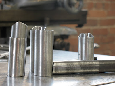
The head tube is the first to be cut. It was rough c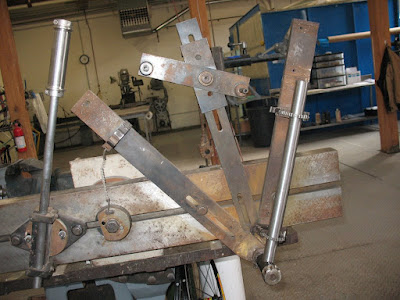 ut to length using a cutoff saw with an abrasive wheel and then chucked into a lathe and faced to square off the end that was cut. The head tube is then placed into the jig between two conical pieces of aluminum that keep it centered on the rod in the front of the jig. The second tube to cut and placed in the jig in the seat tube. The seat tube is rough cut to the approximate desired length and then metered to the proper length at a 90 degree angle using a hole saw equal to the size of the BB shell. This may seem obvious, but it is far too easy to mistakenly grab the hole saw the diameter of the tube being cut rather than the one which the tube is being mitered to join.
Next we cut the top tube. The first miter wa s made in the head tube end to ensure that there would be plenty of material at that end as it will see much more stress than the seat tube due to the long moment arm of the fork acting on it. The seat tube end is then rough cut to the approximated finish length, then mitered to the proper length. After the miter was made, as happened after each miter, the belt sander was used to deburr the outer diameter of each miter, as well as to remove the areas of the tubes that were made excessively thin by mitering them.
The miters in the top tube are more difficult to set up than that of the seat tube. The head tube cut was done at a 93.5 degree angle as shown on the frame blueprint above. It was cut using a hole saw equal to the diameter of the head tube.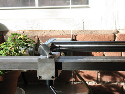 Before the second miter can be made in the top tube we install a piece on the jig to properly orient the tube to ensure that the second miter is cut in the same plane as the first. The piece that we added to the jig is a cylinder the same diameter of the head tube and it swivels freely such that it seats fully in the previously mitered end while allowing the tube to be clamped securely into the mitering fixture. The end with the cylindrical swiveling piece can also slide up and down the fixture to adjust the length of the tube. A scale is on the top of the fixture and allows for quick setup. For this miter the jig was set at 94 degrees, a 30mm hole saw used and the length set to 584.4mm.
The down tube is mitered similarly to the top tubes, only with different angles and hole saws. The one added twist to it is that a down tube of this large a diameter not only intersects the BB shell, but also the seat tube. We approached mitering this tube by first mitering the down tube at the head tube end, then the BB end. Lastly, we used a permanent marker to roughly mark the depth of the necessary notch. The mitering jig was then set to the angle of 55.7 degrees and the hole saw plunged to saw up to the marked length.
The main tubes were then placed in the frame jig to check fit. Since the angle was set on the head tube but not the position we used the top tube and down  tube as guides to places the head tube by sliding it until it fit snugly. We then could check to be sure that all of the miters were tight and to the proper lengths. We measured the lengths of the tubes with a tape measure and inspected the miters visually. The miter in the down tube which provides clearance for the seat tube needed to be adjusted. We had to re-miter it twice to get it right, but it fit nicely when we were done.
Once the fit of the main tubes was verified we prepared them for welding. The insides were cleaned using a die grinder with a sanding drum at each end. Then the inside and outsides were washed with non-chlorinated brake cleaner or lacquer thinner.
Toby had me miter a few scrap pieces of tubing to fit practice welding on. They were mitered to fit and cleaned as the main tubes were. By this time it was 7pm and we decided to call it a day.