Thursday, March 11, 2010

Bike Frame Building Course: Part 1

I'm back from the bike frame building course at Hot Tubes in Shirley, MA and I am very happy with the results. The frame I produced in the class is exactly what I've been wanting, and the experience that I gained is priceless. I have no doubt that I have enough knowledge to make another frame on my own. I'm not saying that it will be as nice a frame, as I won't have anyone there to correct my mistakes in welding, or to remind me of the proper order with which to do things, but it will be a good, sturdy bike frame. It will just probably take much longer, require a lot more finish work to hide ugly welds, and will lack the impeccable paint job of a frame painted by Toby Stanton.

The whole experience was a good one. The shop that Toby has set up in Shirley, MA is quite impressive. It is located in a renovated mill that was once the home to a rope manufacturer. The brick walls, exposed beams, and large windows provide an atmosphere that really makes going back to my cubicle in a windowless factory tomorrow even more difficult. The work are was well organized and clean. The only messes in the place were those made by me, or the two frame builders that Toby let borrow his space as they prepped frames for the North American Handmade Bicycle Show. On day one Toby and I sat down at the PC... er, iMac and designed my frame using a program called BikeCAD. The program is a user-friendly way to quickly input frame dimensions in order to spit out the necessary lengths and angles at which to cut tubes. The frame geometry that we decided to use was a cross between that used on the Ted Wojcik Monkeybutt and the Felt Nine that I demoed at Interbike East early this past fall. I decided to build it around a Fox F29 100mm fork, the dimensional specifications for which can be found on the Fox website if you really dig for them.

Once the geometry was decided upon we were able to start to set up the frame jig. The first step for doing so was to set the bottom bracket drop. Toby's frame jig is made such that the bottom of the main member, once the table of a milling machine, is coincident with the centerline of the dropouts. That means that measuring the BB drop is a simple as using a dial caliper to measure the distance from the bottom of that main member to the center of the BB post. There is a mark on the BB post which makes it easy to find the center. The next step in setting up the jig was to adjust the angles of the arms which hold the seat tube, top tube and the head tube. This was done using a digital protractor using the main member as the reference point on which to zero the protractor.

The head tube is the first to be cut. It was rough cut to length using a cutoff saw with an abrasive wheel and then chucked into a lathe and faced to square off the end that was cut. The head tube is then placed into the jig between two conical pieces of aluminum that keep it centered on the rod in the front of the jig. The second tube to cut and placed in the jig in the seat tube. The seat tube is rough cut to the approximate desired length and then metered to the proper length at a 90 degree angle using a hole saw equal to the size of the BB shell. This may seem obvious, but it is far too easy to mistakenly grab the hole saw the diameter of the tube being cut rather than the one which the tube is being mitered to join.

Next we cut the top tube. The first miter was made in the head tube end to ensure that there would be plenty of material at that end as it will see much more stress than the seat tube due to the long moment arm of the fork acting on it. The seat tube end is then rough cut to the approximated finish length, then mitered to the proper length. After the miter was made, as happened after each miter, the belt sander was used to deburr the outer diameter of each miter, as well as to remove the areas of the tubes that were made excessively thin by mitering them.

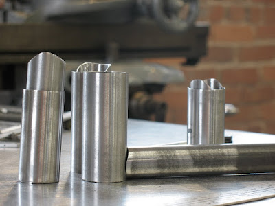
The miters in the top tube are more difficult to set up than that of the seat tube. The head tube cut was done at a 93.5 degree angle as shown on the frame blueprint above. It was cut using a hole saw equal to the diameter of the head tube. Before the second miter can be made in the top tube we install a piece on the jig to properly orient the tube to ensure that the second miter is cut in the same plane as the first. The piece that we added to the jig is a cylinder the same diameter of the head tube and it swivels freely such that it seats fully in the previously mitered end while allowing the tube to be clamped securely into the mitering fixture. The end with the cylindrical swiveling piece can also slide up and down the fixture to adjust the length of the tube. A scale is on the top of the fixture and allows for quick setup. For this miter the jig was set at 94 degrees, a 30mm hole saw used and the length set to 584.4mm.
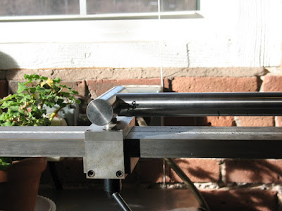
The down tube is mitered similarly to the top tubes, only with different angles and hole saws. The one added twist to it is that a down tube of this large a diameter not only intersects the BB shell, but also the seat tube. We approached mitering this tube by first mitering the down tube at the head tube end, then the BB end. Lastly, we used a permanent marker to roughly mark the depth of the necessary notch. The mitering jig was then set to the angle of 55.7 degrees and the hole saw plunged to saw up to the marked length.

The main tubes were then placed in the frame jig to check fit. Since the angle was set on the head tube but not the position we used the top tube and down tube as guides to places the head tube by sliding it until it fit snugly. We then could check to be sure that all of the miters were tight and to the proper lengths. We measured the lengths of the tubes with a tape measure and inspected the miters visually. The miter in the down tube which provides clearance for the seat tube needed to be adjusted. We had to re-miter it twice to get it right, but it fit nicely when we were done.

Once the fit of the main tubes was verified we prepared them for welding. The insides were cleaned using a die grinder with a sanding drum at each end. Then the inside and outsides were washed with non-chlorinated brake cleaner or lacquer thinner.

Toby had me miter a few scrap pieces of tubing to fit practice welding on. They were mitered to fit and cleaned as the main tubes were. By this time it was 7pm and we decided to call it a day.
Sunday, February 07, 2010

Hot Tubes Bike Building Course

I've been obsessing about bicycles for a few years now. Something about the freedom of riding a vehicle that is powered by only the person driving it really appeals to me. The design and artistry that goes into bike frames and components is also something that I find massively appealing. I've been tossing around the idea of making myself a lugged steel frame for a while now. I've bought, downloaded or borrowed from the library, just about every book on the subject that has every been written. The problem is that brazing requires lots of practice and is best learned from someone with lots of experience. I looked into some frame building courses, but they all seemed to be two weeks long and that would eat up all of my vacation, which would not go over well with the wife. I then stumbled onto a course at Hot Tubes near Worcester, MA that is only a week long. Not only that, but it happens to be fairly close to where I used to live/work and I have a friend in whose guest room I can stay for the week.

The only catch is that due to the compressed course time, the method of frame construction is TIG welding, not brazing. TIG welding has benefits over lugged construction, in that it is faster, potentially stronger, and does not limit the frame geometry to only angles for which there are existing lugs. The drawback is that it lacks some of the artistry involved in intricately carved lugs, which is one of the things that really draws me to hand-built road bikes.

The fact that TIG welding has the benefit of flexible geometry made the decision to make a mountain bike rather than a road bike an easy one. I've been considering getting a 29er mountain bike for a few years now. They have a reputation for being well-suited to northeastern riding and bigger riders. The larger tire diameter rolls over obstacles like the rocks and roots common to New England trails. Also the larger tires provide more traction which is always beneficial.

Initially, I intend to run the bike with a rigid fork and 2x9 gear setup with a bash guard up front. I rarely use the highest gear on my mountain bike so I think I'll be better off without it as I may be able to run a medium cage rear deraileur which should improve shift speed, smoothness and reliability. I have had problems with my current bike jamming the chain resulting in chain breakage, so hopefully some of that will be negated by running a 2x9 or maybe even a 1x9 setup. As far as the fork goes, I haven't really decided on what suspension fork I want to base the frame around. For all I know I may like riding rigid. I think that I'll base it around the Fox F29 with 100mm of travel for the time being and see if I want to add it down the road.

So far I have purchased a few items that I am certain I will need such as a wheelset and brakes. I will purchase the remaining components from Hot Tubes at the end of the class. Toby Stanton, the owner/instructor says that he will sell the components "at catalog prices". Whatever that means. All in all this bike is not going to be cheap, but I think that learning skills such as this from someone with as much experience as Toby is priceless. Sure, I still wish that I could take a course taught by Doug Fattic or someone else, known to be exceptional at fillet brazing and lug work, but I have to start somewhere and Toby's class will give me a starting point from which I will be able to grow my abilities. Best of all, I can skip the initial blundering and have a working, high quality bike that I can be confident in and proud to ride.

I hope to take pictures and document the experience as I go, but as any of the few people who bother reading my blog know, I will probably fail in doing it in a timely manner. There is just always something else to do. I never remember to take enough pictures and have trouble organizing my thoughts in a concise manner such as to describe them to others. Hopefully I'll figure out how to do it in time for the class. It seems like it should be an important enough thing that I may be able to follow through on it.

Sunday, December 20, 2009

Taig Mill: More Upgrades

I had a chance to do a bit more work to the Taig Mill. Along with the new motor I purchased a new X-axis leadscrew, adjustable backlash leadscrew nuts and a bearing block assembly.

The X-axis leadscrew had been damaged in shipping. The damage was not bad enough that it didn't work, but I wanted to get the adjustable backlash nuts to help reduce backlash and since I would have it apart I may as well change the leadscrew. The end of the leadscrew had been damaged enough such that it would probably not work with the CNC conversion later so it would have to be changed eventually regardless.

Changing the leadscrew was pretty simple. First turned unscrewed the two screws holding the bearing block on the end of the X-table. Then I turned the lead-screw out of the leadscrew nut. The leadscrew nut could then be replaced with the new adjustable backlash model. Prior to doing so I cleaned and oiled the gibbs and ways, since it was all exposed and easy to get at that point.


The next step was to remove the crank and the dial from the old leadscrew by first removing the hex nut. Be careful not to allow the key to fall out from the keyway in the shaft if you need to reuse it. It is small and can be very difficult to find on the garage floor. Not that I know, I am just assuming that this would be the case. I next placed the new bearing block on the new leadscrew and assembled the dial and crank onto the new leadscrew. The new leadscrew included a key, a washer and a lock-nut. I've read to be careful not to over-tighten then nut as this can damage the ball bearings in the bearing block. I therefore used care to tighten the nut only until I could feel no more slop in the assembly.


I did find that the key was a little oversized and needed to be filed to fit properly. Aside from that it all fit together quite nicely. One thing that I was disappointing in was the shallowness of the mark on the bearing block which one would use, in conjunction with the dial, to determine the travel of the table. If you look at the picture below you may barely be able to see what looks like a vertical scratch at the 12 o'clock position. This is not much more visible by eye than in the picture and I will have to try to scribe it more deeply later. I realize that this bearing block is intended to be used mainly on CNC machines, but if they were going to go to the trouble of marking it at all they may as well have done it deeply enough to be useful.

Once the leadscrew assembly was together I screwed it onto the X-axis table and slid the table into the ways. I then adjusted the ways until I could feel no play, but the table slid with little resistance. At this point I proceeded to thread the leadscrew into the leadscrew nut. I happened to have bought the 19" leadscrew, despite having the 18" table. This will allow me to upgrade the table size later, but it also allowed easier access to the leadscrew nut for backlash adjustment. I was able to have the table in the ways while having the nut exposed enough to adjust. This is done by loosening the set screw in the middle of the nut and turning the two screws one either side until they were snug. Then you back off of the outer screws by 1/4 turn and snug up the set screw. All said and done, I got the table assembled and backlash was down to about .003" which is way less than it was before. I believe that I can get a little more out if I really fiddle with it, but .003" is fine for manual work. I'll obsess about it once I convert to CNC.


Further improvements I intend to make are to replace the other two leadscrew nuts, and to make and install way covers. After that I'll have to tram everything up and I'll be ready to cut some more chips on her.

Tuesday, November 24, 2009

Taig Mill From Ebay: Update

I'm still chasing the backlash in the table. There seems to be as much as .012" on the y axis. It looks to me as though it is coming from the bearing blocks at the end of the leadscrews where the cranks are mounted. There doesn't appear to be any way to adjust this out. I ordered a new x axis leadscrew and a bearing block assembly as well as the CNC style leadscrew nuts which can be tightened to reduced backlash. I also ordered the 1/5Hp motor which should be an improvement over the 1/8Hp motor that is on it now. It only cost me $30 so I figured it was worth a try. As you can see in the picture below I also got around to wiring and mounting a switch to the Taig. The Taig motor came with a connector wired to it that happens to be the mate to the type of connector that plugs into a PC power supply. That made it really simple to use spare PC power cord to wire it up.


I also managed to wreck the test indicator that I was using to align the vise. I was cranking the handles to move the table to do something and I didn't remove the indicator before doing so. I tend to be really impatient and take shortcuts that end this way all too often. Luckily, the indicator was a $30 cheapy that I bought from littlemachineshop.com rather than a $200-$300 Starret or Brown and Sharp.
I did manage to machine a few pieces out of scrap aluminum that I got from work. I made a few t-slot nuts and two clamps to hold the vise down. In order to clamp the vise down to make those I ground some 1/4-20 carriage bolts to fit in the t-slots and made some clamps on the FDM machine at work. The FDM machine extrudes ABS plastic, so those clamps were not very strong and the vise walked at times, which is why I used them only to make new clamps.
Lee and I got together at his house the other Saturday. I loaded the bio-diesel processor into my truck and dropped it off in one of his garages. I presently have no diesels running, so the ambition to complete the processor is just not there. Lee now has my old Golf and a Rabitamino, so hopefully he'll find the time to get one of them going and the processor up and running too.
After we unloaded the processor we worked on fixing up an old drill press that Lee had because I had none and he had an extra laying around. The press had no power cord, no power switch, and the belt guard had no means of being mounted. Lee fashioned a quick and dirty power switch from a light switch that he hastily tore off of the wall of his garage. He then attached it using some scrap wood that was laying around. Lee doesn't pay much regard for aesthetics, but he gets results.


The mount for the belt guard was a bit more refined as Lee was itching to show me his wood lathe and used it as an excuse to start it up. The drill press is based around a large pipe Lee turned a piece that would fit into the pipe. He then attached a few blocks of wood upon which the guard rests quite nicely. It isn't beautiful but it works better than the nothing that I had before.


I actually used the drill press to drill and tap the holes in the Taig column to mount the power switch. It was much nicer than drilling a crooked hole with the hand drill. I was also able to chuck the tap and turn it by hand to start the tap straight, thus reducing the likelyhood of breaking the tap. Well done, Lee. Thanks for the drill press.

Saturday, October 31, 2009

Taig Mill from Ebay

I won an auction a little Taig mill on Ebay last Friday and it was delivered on Thursday. The packing left a little to be desired, but only because a UPS delivery requires that things be entirely encased in carbonite to protect them from the repeated drops and such that they inevitably encounter.

The mill didn't fair too badly, but the end of the x-axis lead screw was bent slightly and the nut on the end of it was a bit mangled. Everything seems to be alright, but I'm debating putting in a claim since it was insured.

Below is a picture of the mangled box that the mill came in and the end of the lead screw that was damaged. The lead screw does seem to drag a little on that end, so perhaps it will be worth calling UPS.


I did my best to clean the gibbs and ways and lead screws, and that made a big difference on the way that the mill table moves. Aside from the little bit of drag on the x axis where the lead screw was bent, the table moves pretty smoothly.

It looks as though this is on older version of the Taig mill, as the color is grey not blue and the gibbs use a different adjustment method than the ones that I have seen pictured elsewhere. I think that it will work just fine for me regardless. I do need to purchase a few items before I can do much with it. The vise that was included is pretty old and crappy. I will also need to buy some t-nuts and other means of holding work down.

The motor on the mill also doesn't appear to be the one currently sold with the mill. It has some problems spinning up with the belts in the highest speed position. It seems that the motor lacks the low speed torque to get the spindle going unless the belt is in the positions that give it a lower gear ratio. I'll see if I can come up with a remedy for that. The motor also came wired directly to a power cord, without a power switch in between. I intend to get a suitable switch for it eventually but for now I came up with a temporary solution. My garage only has a single outlet in it and it is not near where I want to use the mill. There is, however, a switch that goes to an outdoor outlet near where the mill is that I was able to easily tap into to add and outlet that I can switch on and off in the meantime.

I'm looking forward to getting this thing up and going. I have a few designs for LED bike lights that I intend to make with it. I'll post the designs when I get around to it.

Tuesday, October 13, 2009

Bike Light Build: Part Three - Milling around


I've never really used a milling machine before, aside from using it as a glorified drill press. I decided that the bike light project was worth giving it a try. I needed to mill a 1/8" thick piece of aluminum into a 7/8" square. It was a pretty unambitious job, but you need to learn to walk before you can run, right? I won't go into a ton of detail about how I did it and whatnot, since I am by no means approaching being an expert. I am, in fact, the opposite. I know just enough to not hurt myself. Not this time anyway.

I was actually surprised at how easily the aluminum cut on the Bridgeport. My few previous attempts at milling had pretty poor results as I was trying to cut steel with dull end mills and absolutely no clue what I was doing. I have since learned a bit more of the proper technique. I still struggle with knowing which direction the slides move when you turn the handles, but I assume that I have the capacity to learn that with more experience.

I will detail later what this piece will be used for. Right now I'm just going to bask in the glow of knowing that I turned handles on a Bridgeport and got more than a squealing noise, hot discolored chips, and a mangled piece of scrap from the endeavor.

Saturday, October 10, 2009

Bike Light Build: Part Two


I got around to playing with the light and the bench power supply last night and it appears that the light shows little or no dimming until the voltage drops below 12V. This means that in mild/warm temperatures I could possibly use NiMh batteries two, without going to the added trouble of buying two 8.4V packs instead of the standard 7.2V packs. At least that is what I have gleaned from wikipedia's information on NiMH batteries. The only other concern is the amperage draw, but I think that the sub-C size cells found in RC battery packs can handle the 500mA draw of the light, and then some.

Today I started building the body of the light with 1" square aluminum tubing that I bought at the hardware store down the road. I started with a 2" long section, which I then notched out so that a 7/8" long section of square tube could be held inside the notch.

I did this by first using a hacksaw to slit down the sides of the tube adjacent to the inner wall, up to a line that I had scribed one inch down the tube.


Next I drilled holes in the tube along the side of the scribed line where I wanted to remove material.


I then used a pair of vice-grips to break off the material at the line of drilled holes.


The next step is to file the bottom and sides flat. Then a piece of square tube is cut to 7/8" and filed to fit into the notch.

I was going to use a piece of aluminum extrusion intended to be a shelf braket as heat sinks, but then I remembered that I had some PC heat sinks that I never used on the PC in our office. I proceeded to cut those to two inches long and added a chamfer on one top corner. The picture below shows the pieces placed together as I intend them to fit.


I also placed an order with Newegg.com for some Arctic Alumina adhesive(AAA). AAA is thermally conductive, commonly used to attach heat sinks to CPU's and such. It has a good reputation for being a tough adhesive too, so I will at the very least use it to adhere the LED and heat sinks to the body. I will probably use JB Weld for more structural joints.

Next up we will finish constructing the body...

Friday, October 09, 2009

Bike Light Build: Part One


Just a few quick note about my latest project. I'm hoping to actually document this one in a useful manner, so bear with me. I've done a little bit of research about DIY lights for mountain biking and finally decided to get around to making one. Fall is upon us and soon there will be little to no chance that we will see the sun for months on end. I will therefor need something to light my path while biking.

I had considered going the cheap route of using a halogen light, but the run time is abysmal compared to other options, such as LED and HID. HID is simply stupid expensive, so I decided to go with an LED. After reading a website all about such lights here, I decided to go with a Cree MC-E emitter from ledsupply.com. The MC-E is actually four emitters closely packed together under one lens and it comes pre-mounted on an aluminum plate to help dissipate heat. The emitters are wired in series which means the forward voltages must be added together, resulting in a Vf of 12.8-13.2. The current is shared by the emitters and I will supply that with a Luxdrive Buckpuck with which I can provide a regulated 500 mA. I chose the wired model, with the potentiometer to vary the current from 0-100%.

To test the Buckpuck and LED I soldered some speaker wires that I scrounged from a box of stereo stuff I had in the closet. I put some alligator clips on those to aid in testing as well. I wired the Buckpuck to my regulated power supply and set the PS to 14.4V which is the voltage that I can get from two 7.2V Ni-Cd battery packs that I bought for my remote control car, when they are wired in series. I then attached the clips on the LED to the Buckpuck outputs and turned on the PS. Voila! Blinding frigging light. Seriously, don't look directly at this thing. At 350 mA this LED throws approximately 430 Lumens and I was driving it at 500 mA which should give it a 30% increase in flux. That is truly bright. I didn't leave the light on for long as it was not attached to any heat sinks and even an LED will heat up when driven at 6.5 watts. I just wanted to verify that everything worked anyway.

Next step... check to see how low a voltage this thing can be driven at so that I can be sure that the battery packs I have will work even when low, or if I need something with more than a nominal 14.4V.

Monday, August 24, 2009

Be vewy quiet, I'm hauling wabbit


I finally got around to hauling the Rabbit up to Maine for Jon to do some work on. It has been in Lee's barn for about 4 years now. In that that time it grew some mold on the interior and provided sanctuary for countless mice. Overall I think that is it very salvageable. Jon will put it on the lift and determine whether or not I am right. I didn't get a chance to try and start the bunny. Instead I scrubbed the mold off of the interior and vacuumed the mice nests out of the engine compartment and glove box. The battery was too far gone to even take a charge and I didn't have time to check the airbox to see if the mice had taken up residence in there as well. Jon will just have to do me the huge favor of doing that for me if he decides that it is worth the hassle.


I neglected to take pictures of the mouse nests, but below is a picture of the mold growing on the driver's side door panel.


I also didn't take pictures of the interior after I washed it, but it cleaned up pretty well. I used a mixture of water, bleach and dishwashing liquid. I wore a respirator while doing this too lessen the likelyhood of getting a respiratory infection. Hopefully it was worth the trouble. I'll post Jon's diagnosis as we go.

Friday, June 26, 2009

How to make waxed cloth

The wife found a project that she wanted to try doing and she enlisted my help, as usual. What she wanted to do was to make a product that she had seen online. The product was essentially cloth replacements for ziploc bags. These bags are to be waterproof, machine washable, and most importantly, pretty looking. Apparently, the products that she had seen had used a vinyl liner to waterproof them. As far as I know, vinyl is not a heathy substance to have near food as it offgasses formaldehyde. I informed her of this and she did some research to find alternatives. After shooting down all of the synthetic fabrics that popped up we decided on waxed cotton. Impregnating organic cotton with beeswax seemed like a very nontoxic and eco-conscious fabric to use.
I'm far too lazy to find the website where we found the instructions for impregnating the fabric with wax, but I will show here how it was done by us.


The first step is to cut a piece of craft paper, or a brown paper bag, and aluminum foil at least as long as the piece of cloth, and at least twice as wide. You want to be able to fold the foil and paper like a soft taco to with the foil and paper in lieu of tortilla, and the cloth and wax in lieu of delicious taco meat. MMMmmm tacos....


The next step is to evenly spread wax shavings on top of the cloth. We did this by using a crappy steak knife to scrape wax off of the big block and onto the cloth.


Next fold the taco... I mean foil and paper around the cloth and use an iron on medium heat to melt the wax. We found that if you go very slowly it gives the cloth time to soak up the wax and impregnates it more evenly. Quickly remove the cloth and allow to cool. Voila! Waterproof fabric that won't leach death into your food.

Up next... Adventures in sewing